A malfunctioning Mass Air Flow (MAF) sensor can significantly impact your car’s performance, leading to poor fuel economy, rough idling, and even engine failure. Understanding how this crucial component works and how to diagnose problems is essential for any car owner. This guide provides five straightforward tests you can perform to determine if your MAF sensor needs attention, empowering you to troubleshoot effectively and potentially save on costly repairs.
We’ll explore the function of the MAF sensor, its common failure points, and the practical steps involved in each diagnostic test. From visual inspection to more involved checks, we’ll provide clear instructions and explain how to interpret the results. By the end, you’ll be equipped to confidently assess the health of your MAF sensor and take appropriate action.
Understanding Mass Air Flow Sensor Function and Failure Modes
The Mass Air Flow (MAF) sensor plays a crucial role in modern vehicle engine management systems. It measures the amount of air entering the engine, providing this vital information to the Engine Control Unit (ECU). This data allows the ECU to precisely control the fuel injection system, ensuring the optimal air-fuel mixture for efficient combustion and reduced emissions. A malfunctioning MAF sensor can lead to a variety of drivability issues and potentially damage the engine.
MAF Sensor Function in Engine Control
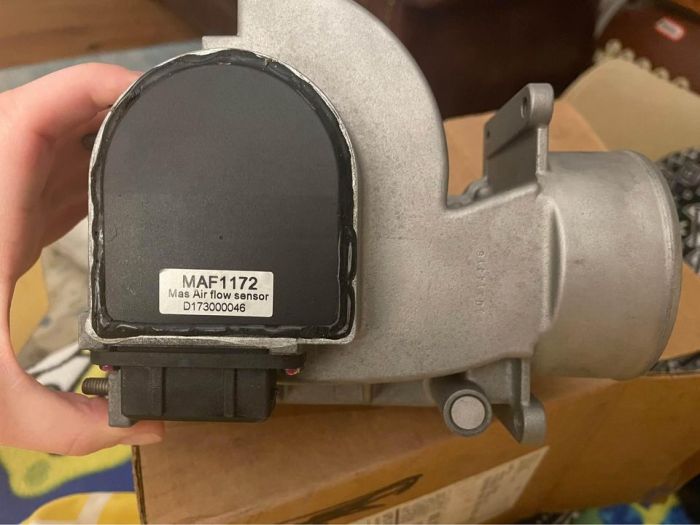
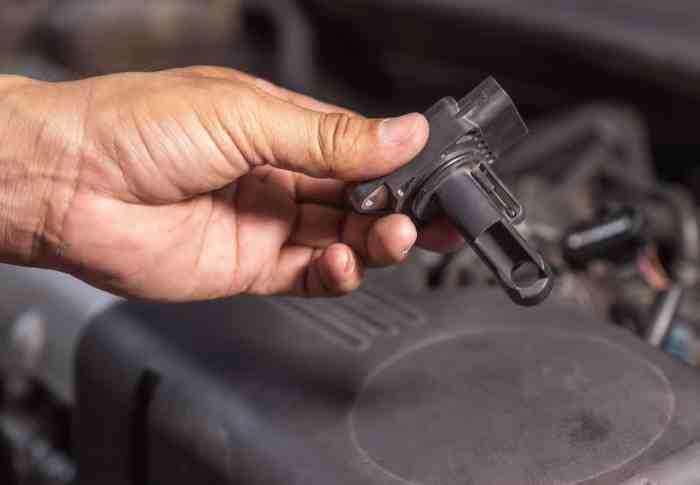
The MAF sensor is typically located in the intake air duct, before the throttle body. It utilizes various technologies, most commonly hot-wire or hot-film, to determine the mass airflow rate. A hot-wire sensor uses a heated wire whose temperature changes depending on the airflow. The ECU calculates the airflow based on the amount of electrical current needed to maintain the wire’s temperature. Hot-film sensors operate on a similar principle but use a thin film instead of a wire. This data is then used by the ECU to calculate the appropriate amount of fuel to inject, optimizing the combustion process for power, fuel economy, and emissions.
Common MAF Sensor Failure Modes
Several factors can lead to MAF sensor failure. These sensors are delicate and susceptible to contamination from oil, dirt, or other debris. Physical damage from impacts or improper installation can also occur. Over time, the sensing element can degrade, leading to inaccurate readings. Common failure modes include a complete sensor failure resulting in a “no signal” condition to the ECU, or a gradual degradation of the sensor’s accuracy leading to increasingly inaccurate airflow readings.
Comparative Analysis of MAF Sensor Types
While both hot-wire and hot-film MAF sensors perform a similar function, there are subtle differences. Hot-wire sensors are generally less expensive to manufacture but can be more susceptible to damage from contamination. Hot-film sensors, while more robust and resistant to contamination, are typically more expensive. Both types are prone to failure due to age and exposure to harsh environmental conditions. The choice between these types often comes down to cost considerations and the specific application requirements.
Common MAF Sensor Problems and Symptoms
| Problem | Symptoms | Possible Causes | Diagnostic Steps |
|---|---|---|---|
| Sensor Contamination | Rough idle, hesitation during acceleration, poor fuel economy, check engine light | Oil buildup, dirt, debris | Visually inspect the sensor for contamination; clean with MAF sensor cleaner; retest. |
| Wiring Issues | Complete engine failure, no start condition, check engine light | Damaged wiring, loose connections, short circuit | Inspect wiring harness for damage; check for continuity and proper voltage at the sensor connector. |
| Sensor Degradation | Poor fuel economy, rough idle, hesitation, check engine light, engine misfires | Aging sensor, exposure to extreme temperatures | Compare sensor readings to manufacturer specifications; replace the sensor if readings are outside acceptable range. |
| Sensor Failure | Engine stalling, erratic idle, poor performance, check engine light | Internal sensor failure, physical damage | Use a scan tool to check for diagnostic trouble codes (DTCs); replace the sensor. |
Five Diagnostic Tests for a Faulty MAF Sensor

Diagnosing a malfunctioning Mass Air Flow (MAF) sensor can be crucial for resolving drivability issues and optimizing engine performance. A faulty MAF sensor can lead to poor fuel economy, rough idling, and even engine misfires. The following tests offer a systematic approach to determining the health of your MAF sensor.
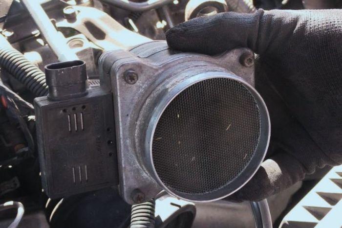
Visual Inspection of the MAF Sensor
A simple visual inspection can sometimes reveal obvious problems with the MAF sensor. This non-invasive initial check can save time and effort before proceeding to more involved tests.
- Carefully locate the MAF sensor. It’s usually found in the air intake system, between the air filter and the throttle body.
- Inspect the sensor for any physical damage, such as cracks, loose connections, or visible debris on the sensor element (the hot-wire element is extremely delicate and should not be touched).
- Check the wiring harness for any signs of damage, such as frayed wires, corrosion, or loose connections. Securely reconnect any loose connections.
- Note any unusual discoloration or signs of burning around the sensor housing.
MAF Sensor Resistance Test
This test measures the electrical resistance of the MAF sensor’s internal circuitry. Variations from the manufacturer’s specified resistance range suggest a potential problem. A multimeter is required for this test.
- Disconnect the MAF sensor’s electrical connector from the wiring harness.
- Set your multimeter to the ohms (Ω) setting.
- Carefully probe the multimeter leads onto the appropriate terminals of the MAF sensor connector (consult your vehicle’s repair manual for the correct terminals).
- Compare the measured resistance to the manufacturer’s specifications found in your vehicle’s repair manual or online resources. Significant deviation indicates a possible faulty sensor.
Voltage Check of the MAF Sensor
This test measures the voltage signal produced by the MAF sensor when the engine is running. The voltage should change smoothly as the engine speed varies. An erratic or non-responsive voltage suggests a malfunction.
- With the engine running, carefully connect the multimeter’s leads to the appropriate terminals of the MAF sensor connector (consult your vehicle’s repair manual). Set the multimeter to measure DC voltage.
- Observe the voltage reading. It should fluctuate smoothly as the engine RPM changes. A consistently low or high voltage, or a voltage that doesn’t respond to changes in engine speed, points towards a problem.
- Observe the voltage reading while smoothly increasing and decreasing the engine’s RPM.
- Compare the voltage readings to the expected range specified in your vehicle’s repair manual or online resources. Significant deviations indicate a potential issue.
Performance Check with a Scan Tool
A scan tool capable of reading live data can provide valuable insights into the MAF sensor’s operation. This method allows for a dynamic assessment under various engine conditions.
- Connect a scan tool to your vehicle’s OBD-II port.
- Retrieve live data, specifically focusing on the MAF sensor readings (often labeled as “MAF” or “Mass Air Flow”).
- Observe the MAF sensor readings as you vary the engine speed and load. Erratic or unusually low/high readings, compared to expected values, indicate potential sensor malfunction.
- Compare the readings to expected values found in your vehicle’s repair manual or online resources. Significant deviations may suggest a malfunctioning sensor.
Comparison Test (with a known good MAF sensor)
This involves swapping your MAF sensor with a known good one from a similar vehicle (same make, model, and engine). If the problem resolves, the original sensor is faulty. This test offers conclusive proof.
- Obtain a known good MAF sensor from a reputable source or a similar vehicle.
- Carefully disconnect the suspected faulty MAF sensor and install the known good MAF sensor.
- Start the vehicle and observe if the symptoms have been resolved. If the problem is resolved, the original MAF sensor is the likely culprit.
- If the problem persists, other components may be at fault.
Interpreting Test Results and Troubleshooting
Interpreting the results of the five diagnostic tests for a faulty mass airflow sensor (MAF) requires a systematic approach. Understanding the expected readings for each test and recognizing potential sources of error are crucial for accurate diagnosis and effective troubleshooting. False positives and negatives can arise from various factors, including faulty testing equipment, incorrect connection procedures, and other underlying vehicle issues. This section details how to interpret the results, identify potential pitfalls, and troubleshoot based on the findings.
Interpreting Visual Inspection Results
A visual inspection of the MAF sensor should reveal any obvious physical damage, such as broken wires, loose connections, or visible debris obstructing the sensor element. A clean, undamaged sensor suggests the problem lies elsewhere. Conversely, a visibly damaged sensor strongly indicates the need for replacement. However, a seemingly clean sensor doesn’t automatically rule out a malfunction; further testing is necessary for confirmation. For example, a small crack in the sensor housing might not be immediately apparent but could still affect its performance.
Interpreting Voltage Measurement Results
The voltage reading from the MAF sensor should fall within the manufacturer’s specified range, typically between 1 and 5 volts. A reading outside this range suggests a problem. A consistently low voltage might indicate a wiring issue or a failing sensor, while a consistently high voltage could point to a short circuit or a faulty sensor. For instance, a reading consistently at 0V would suggest a broken wire or a disconnected sensor. However, intermittent low voltage might be caused by a loose connection that is only sometimes making contact.
Interpreting Resistance Measurement Results
Resistance measurements provide insight into the sensor’s internal circuitry. A reading significantly different from the manufacturer’s specifications suggests a problem. Open circuits will result in infinite resistance, while short circuits will show near-zero resistance. For example, if the expected resistance is 10 ohms and the measurement is 1000 ohms, a fault is likely. However, variations in temperature can slightly affect resistance, so comparing the reading to the manufacturer’s specifications at the operating temperature is crucial.
Interpreting Airflow Meter Comparison Results
Comparing the MAF sensor’s reading to a known good airflow meter helps isolate the problem. If both meters show similar readings under the same conditions, the MAF sensor is likely functioning correctly. Discrepancies indicate a malfunctioning MAF sensor. For example, if a known good MAF sensor shows a reading of 10 grams/second, and the suspect sensor shows 5 grams/second under identical conditions, the suspect sensor is faulty. However, ensure both meters are calibrated and functioning properly.
Interpreting Diagnostic Trouble Code (DTC) Results
A DTC related to the MAF sensor confirms a problem. The specific DTC code provides further information about the nature of the malfunction. For instance, a P0101 code usually indicates a MAF sensor performance issue. While a DTC is strong evidence, it doesn’t pinpoint the exact cause. Further testing might be necessary to differentiate between a faulty sensor and a related wiring problem.
Troubleshooting a Faulty MAF Sensor
The flowchart below Artikels the decision-making process based on test results.
Troubleshooting Flowchart
Closure
Diagnosing a faulty MAF sensor doesn’t have to be daunting. By systematically following the five tests Artikeld in this guide, you can pinpoint the problem and determine the best course of action. Remember to always prioritize safety and consult a professional mechanic if you’re unsure about any step. Empowering yourself with this knowledge allows for timely repairs, ensuring optimal engine performance and extending the life of your vehicle.